 What is a Point Cloud?
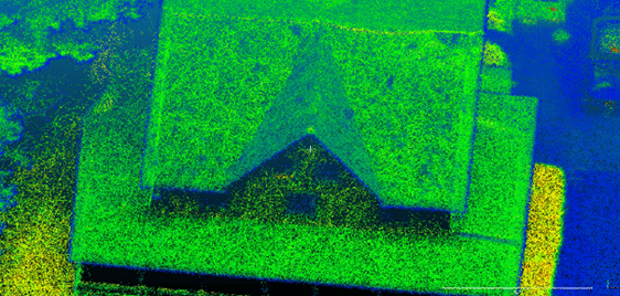
A point cloud is created by scanning an area with a 3D Laser Scanner. This scan is then imported into post-processing software (unless desired accuracy is obtained in real-time) where errors are removed. After processing the data, modeling software is used where the clouds can either be geo-referenced to a ground plane or manipulated locally without reference. From here, point clouds are then exported into computer-aided design (CAD) or building information modeling (BIM) systems, where they can be manipulated further, generating meshes and applying boundary conditions to generate accurate and realistic 3D models (1). Even with an explanation of a point cloud it is still hard to understand what a point cloud is if one has not been familiarized with the technology. When the user performs a scan, the laser scanner sends out beams of light in many different directions. As these light beams are reflected to the scanner, the system uses a datalogger to record reflected positions as localized vectors. These scan files can contain as little as thousands of logged vectors or as many as millions, if not billions depending on the scanning project at hand. These 3D vectors are then used in the post-processing software to generate a visualized point cloud.
LiDAR Scanning
A laser scanner is a device that uses laser technology to emit light through optical amplification. Light detection and ranging (LiDAR), on the other hand, is a process specifically used for surveying surfaces and utilizes laser technology to facilitate its results. LiDAR uses penetrating pulses of laser light and determines the distance to the target through sound navigation ranging (SONAR). These pulses reflect from backscattering which is typically a diffuse reflection due to scattering (2). These pulses facilitate the process of measuring the structure and arrangement of the atmosphere. LiDAR is a SONAR technique meaning that it uses the echo propagation time of a probe beam to measure the distance between the device and the target (3).
With this in mind, LiDAR is able to illuminate very specific targets and have a very precise point cloud. There are two types of LiDAR detection schemes: direct energy detection or incoherent detection and coherent detection. Coherent detection is more sensitive than direct energy detection and can operate at lower power but requires complex transceivers. Both systems use pulse models: either micro pulses or high energy pulses.
Point Cloud Referencing vs. Registration
Referencing
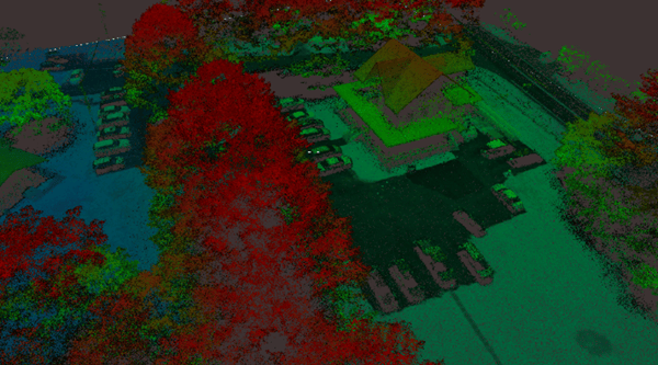
Referencing data is the act of taking data points stored in a local frame of reference and making them known globally (geo-referencing). This is commonly used in applications that analyze point clouds after the scanning is completed instead of using them in real-time to accomplish a task (such as autonomous navigation or threat recognition). Common applications that use referencing are topography, surveying and other scanning applications where sub-centimeter level accuracy for point clouds are not needed.
Direct-Georeferencing is the most common method of referencing. In this method, an on-board navigation system tags individual data points with a latitude and longitude position in real-time. This makes post-processing and cloud manipulation much faster.
Registration
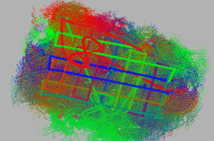
The registration of point clouds is the act of aligning sets of point clouds with one another to create a more accurate and precise model. This is commonly used in simultaneous localization and mapping (SLAM) applications where computer vision algorithms are using active predictions to generate a cloud with as little cloud thickness as possible. Many of the applications that utilize this method of scanning do not store data for processing, but instead they use real-time results for applications such as collision avoidance, autonomous navigation and object recognition.
The most common form of point cloud registration is to use artificial targets. These targets can be patterned (similar to a checkerboard or with a retro-reflective dot), a geometric object of known dimensions, or a combination of both. These methods provide a common set of observed data points from which estimates based off these multiple passes or scans can be derived (4). It is found that target-based registration can provide high accuracy registration as long as the survey network design rules are complied with. While this method can produce highly accurate results, it is very time-consuming to plan and survey targets. As a result, survey professionals have had a growing interest in automated alternatives that involve the use of GNSS receivers and accurate inertial measurement units.
Accuracy Problems
Human or Object Movement
The movement of people or objects within an area will always cause localized inaccuracies within a scan. The use of artificial targets can prevent inaccuracies but are time consuming to set up. Targetless scans (uses ground control points instead of internal GNSS receiver) build off each other so if one scan is of poor quality, it can impact the entire model (5). When outdoors, where movement is more prone to occur, scans can return noisy, inaccurate data.
For example, wind will cause trees to sway, cars driving by may distort scans; and without consistent reference points, too many of these occurrences can make it very difficult for targetless registration/referencing to be accurate. Movement problems can be overcome within the context of natural stationary reference points. Recent algorithm advancements have made this a repeatedly achievable and accurate outcome. For targetless scans to be accurate, they require a significant amount of overlap. This issue is consistent for targeted scans but can be more easily avoided through strategic placement of artificial targets.
Time
As mentioned, the necessity for high overlap between targetless scans is another source of difficulty. Traditional targetless registration requires up to 60% overlap in order to ensure accurate alignment. Presently, advanced modern systems have lowered this need down to 30%. Even if it takes more time to achieve the necessary overlap, it is much less time than it takes to set up artificial targets for scanning. A bigger time issue comes from the amount of time it takes to process that increased amount of data. This problem is amplified by the fact that it takes more time per scan for software to identify natural features than artificial targets. The biggest problem is that traditional software requires regular manual inputs, demanding constant professional supervision. These issues are why many people have switched to using internal GNSS receivers inside their payloads. Timestamps allow for increased correction quality as well as allows correctional software to increase the speed at which data can be processed.
Applications
Inspection
 Power Lines
Regular inspections of power lines are critical for securing uninterrupted electricity distribution. In the past, ground inspection methods performed by a group of surveyors were utilized. This method is very labor-intensive, time-consuming, and potentially dangerous for teams inspecting lines located in hazardous terrain. As of late, energy service providers have begun to turn to automated LiDAR equipped unmanned aerial vehicles (UAV) payload technology. This has proven to be an effective alternative to land inspection and produces highly accurate point cloud data through PPK and RTK (6). With the use of Inertial Labs INS-B-OEM, surveying power lines is both a time-efficient and cost-effective alternative to land surveillance.
 Construction Sites
LiDAR systems have a wide range of applications throughout all phases of construction sites. Even before construction, it is important to survey the site to confirm that all structures can foundationally exist on the terrain without any structural issues caused by rockslides, uneven terrain or sink-holes (7). An efficient way to survey structures and terrain accurately is by using drone aerial surveillance. LiDAR payloads can also be a useful tool in the visualization of elevation as color schemes can be added to the point clouds indicating changes in elevation. As a result, the time it takes to create x, y, and z coordinates for structures has been greatly reduced, meaning that 3D analysis of the ground and structures is much easier.
 Railways
The quality of rail tracks can be thoroughly inspected through LiDAR-based systems. Accurate and precise point clouds allow users to identify potential weaknesses in the track as well as crack propagation and other damages. It is from this data that rail deterioration models can be derived, allowing for predictive maintenance and the insurance of rail quality (8). Deterioration models take historic data, current track conditions captured from LiDAR, and traffic data to identify geometric defects and model track degradation analytics.
Navigation and SLAM
Robots, or other autonomous systems cannot always rely on GNSS for navigation purposes, especially indoors where GNSS signals are not always reliable. Whether indoors or outdoors, GNSS-based navigation is not sufficiently accurate for systems that need to have precision within a few centimeters to operate safely. Systems requiring centimeter level precision rely on simultaneous localization and mapping (SLAM) to map and discover their surroundings. Systems utilizing SLAM build their own maps in real time. These systems can find their own position by aligning sensor data that they collect with previously collected data to build out a map for navigation. Robots using SLAM continuously gather data at a rapid rate. Camera images are taken about 90 times per second for depth-image measurements, while LiDAR images are taken about 20 times per second to precisely identify range (9). Raw sensor data undergoes a process called sensor fusion employed by a Kalman filter (for more info on sensor fusion see our white paper) which gives a better estimate of how the robot is moving.
Topographic Surveying
Some coastal applications include monitoring shoreline changes, tracking sediment movement, and mapping coastal features. Data from these applications allow us to accurately map coasts and prevent major erosion.
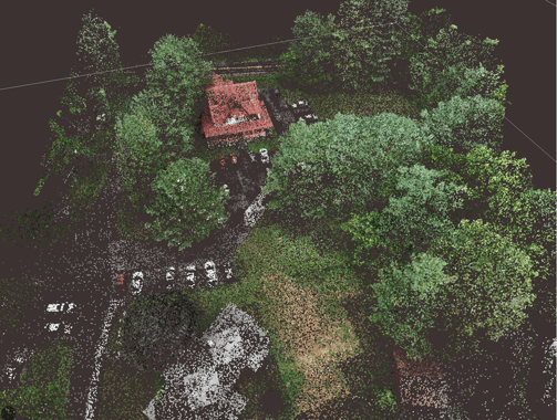
We can manage natural resources by monitoring land use, mapping wetlands, and charting wildlife ecosystems. This can be used to minimize environmental damage from urban growth and help determine the best ways to protect natural resources and positively impact the environment.
Corrections and Modeling Software
Real Time Kinematic (RTK)
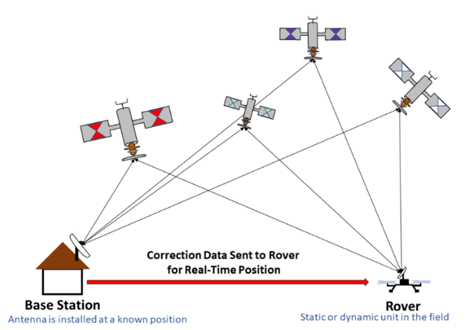
Georeferencing is the idea that the internal coordinate system of map or aerial image can be compared to a ground system of geographic coordinates. Georeferencing allows the user to see ground coordinates, distances, and areas. In other words, georeferencing allows the user to link a local coordinate system to a global coordinate system. Data that is captured using real time kinematics (RTK) means that the data has not been post-processed before it is used to generate point clouds (10). To increase accuracy of point clouds in real time, the use of RTK corrections can be very helpful. At Inertial Labs, we use an RTK corrections casting software called NTRIP Caster®, to send correctional data to the rover and directly georeference our data with the data of a local base station. Adding RTK corrections to a UAV LiDAR solution automatically logs precision points in space as the solution scans. In fact, using RTK corrections (or any GPS service/signal) removes the need for ground points as it accurately measures position to as low as 1cm + 1ppm (without post-processing). Enabling RTK corrections is a good cost-effective solution to increase the accuracy of your point cloud, especially when compared to buying an upgraded drone or UAV.
Post Processed Kinematic (PPK)
Post-Processed Kinematics (PPK) is the alternative to RTK in which positioning accuracy does not happen in real time but is achieved through correctional services that are applied after the data is captured. The added benefit of utilizing PPK is the fact that the rover does not require additional hardware on-board to get position accuracy, nor does it require the use of a dual antenna GNSS receiver (which many applications require to have accurate heading) (11). PPK software has the ability to analyze data from start to finish, and from finish to start. By doing this, the software can catch and identify inconsistencies and correct them much better than any RTK correction could.
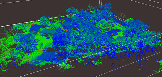
When post-processing, both the ground station and the UAV record GNSS data, which is then combined with inertial data and processed to create accurate positioning and orientation data. PPK can be used as a strong backup to RTK, and like RTK, PPK does not require ground control points to accurately map positioning. Similarly with RTK corrections, PPK corrections work best when the rover is closest to the base station. However, when operating at long distances from the base station, atmospheric errors can occur. Fortunately, many PPK software today have built in functions to help mitigate this error build up. Below are examples of a point cloud generated from PPK.
Inertial Labs Line-Up Point Cloud Comparison
The Inertial Labs team decided it was time to compare what kind of point cloud accuracy was achievable when combining different LiDAR scanners with the Inertial Labs INS-B-OEM. This complete system allows for real time datalogging capabilities at a price point well below the market average that is designed to handle both aerial and ground-based scanning applications. Below is a chart displaying the PPK and RTK accuracies of these systems. Dataset distributives as well as point clouds are available from the Inertial Labs Sales and Marketing Team upon request.
|
LiDAR |
PPK Accuracy (cm) |
RTK Accuracy |
|
Livox Mid-40 |
5 |
7 |
|
Livox Horizon |
12 |
14 |
|
Velodyne VLP-16 |
15 |
18 |
|
Quanergy M8 |
26 |
30 |
The Value of Point Cloud Technology
Precise Modeling
LiDAR-based point clouds can have an accuracy as low as 2 centimeters as long as the user is willing to pay for it (12). For these solutions, once a scan is completed, results typically do not need to be checked in order for them to provide an accurate 2D or 3D model. As a result, the operator gets comprehensive information regarding an existing structure or landscape without the need for a post-processed solution. This reduces the need for users to request additional information that in turn prevents work delays. In addition, they are very effective for measuring dimensions of structures, and it helps the user to understand the spatial relation between the different parts of the structure.
Fast and Cheap Survey Method
Point cloud surveillance is the fastest way to survey existing structures at a site as it removes the need for large land survey teams and can be an automated process. All that is required for an accurate point cloud model is a scanner, an inertial navigation system, and a datalogger. Once this model is made, there is no need for additional site visits for more data as the point cloud model is entirely sufficient, especially when used with a photogrammetric solution. As a result, the time spent on the site for the user is drastically reduced. In addition, the speed and accuracy of this data helps companies reduce the time they spend focusing on surveillance and eliminates the monetary impact of inaccurate manual surveillance.
Conclusion
As mentioned earlier in the article, point cloud technology is continually used in a variety of fields and applications. The use of the Inertial Labs INS-B-OEM in conjunction with a LiDAR system mounted on a drone is the perfect recipe for businesses looking to survey railways, construction sites, and power lines. With the aided help of RTK or PPK corrections, our solutions help provide these businesses with accurate mappings, allowing for the optimization of financial and human resources.

Bibliography
1. Thilmany, J. (2018, February 27). What Is a Point Cloud? Constructible.Trimble.Com. https://constructible.trimble.com/construction-industry/what-is-a-point-cloud
2. admin. (2019, October 4). Differences between LIDAR and Laser. LIDAR and RADAR Information. http://lidarradar.com/info/differences-between-lidar-and-laser
3. Wikipedia Contributors. (2019, October 13). Lidar. Wikipedia; Wikimedia Foundation. https://en.wikipedia.org/wiki/Lidar
4. Thomson, C. (n.d.). Improve point cloud registration with targetless scanning. Info.Vercator.Com. Retrieved July 29, 2020, from https://info.vercator.com/blog/improve-point-cloud-registration-with-targetless-scanning#:~:text=The%20advantage%20of%20this%20form%20of%20point%20cloud
5. Thomson, C. (n.d.-b). Speed vs. accuracy: Compromise when it comes to point clouds? Info.Vercator.Com. Retrieved July 29, 2020, from https://info.vercator.com/blog/speed-vs.-accuracy-do-you-need-to-compromise-when-it-comes-to-point-clouds
6. Power Line Inspection Using Airborne LiDAR - GreenValley International. (n.d.). Greenvalleyintl.Com. Retrieved July 29, 2020, from https://greenvalleyintl.com/applications/power-line-inspection-using-airborne-lidar/
7. admin. (2019a, August 18). Uses of LIDAR In Construction. LIDAR and RADAR Information. http://lidarradar.com/apps/uses-of-lidar-in-construction
8. Taheriandani, M. (2016). The Application of Doppler LIDAR Technology for Rail Inspection and Track Geometry Assessment. Vtechworks.Lib.vt.Edu. https://vtechworks.lib.vt.edu/handle/10919/70976
9. Martin, S. (2019, July 25). What Is Simultaneous Localization and Mapping? What Is Simultaneous Localization and Mapping? | NVIDIA Blog. The Official NVIDIA Blog. https://blogs.nvidia.com/blog/2019/07/25/what-is-simultaneous-localization-and-mapping-nvidia-jetson-isaac-sdk/
10. Flying camera to surveying tool: RTK/PPK drone upgrades. (2020, February 10). Pix4D. https://www.pix4d.com/blog/rtk-drone-upgrade
11. Analyzing PPK solution and logs - Reach M+ docs. (n.d.). Docs.Emlid.Com. Retrieved July 29, 2020, from https://docs.emlid.com/reachm-plus/common/tutorials/analyzing-logs/
12. Point Cloud Modeling Technology For Renovation. (2018, July 30). BluEntCAD. https://www.bluentcad.com/blog/benefits-of-point-cloud-technology/
Trademark Legal Notice: All product names, logos, and brands are property of their respective owners. All company, product and service names used in this document are for identification purposes only. Use of names, logos, pictures and brands does not imply endorsement. Livox, Velodyne, Quanergy are trademarks of its affiliates or its respective owners, registered in many jurisdictions worldwide.

