What is a Remote Weapons Station?
 A Remote Weapons Station (RWS) is a remotely operated weapons platform that utilizes light and medium caliber artillery shells. Typically, an RWS contains sensing components (angular rates, accelerations, etc.), motor drives, a turret, and a computer. Today, companies like Electro Optic Systems Pty Ltd are patenting next generation Electro Optic RWS that are gyro-stabilized, combat ready, and built for precision targeting(1).
Since the two most important characteristics for an RWS are aiming speed and accuracy, advanced methods of stabilization are required to ensure that targets are correctly dealt with. The most important component in this task is the gyroscope.
Gyroscopes for Stabilization
The gyroscope is used to account for the pan and tilt model used by RWS. Spherical data (theta, phi, and the range - rho) is key to be able to stabilize this system because of the nature of the application. Angle theta is used to stabilize the tilt motor, angle phi is used to direct the pan motor and rho (distance) is typically calculated using a laser range finder(2).

The task for improving the stability of weapons stations is a job that will always be adapting. Creative uses of both sensors and structures are slowly increasing accuracy over distance. The United States Army filed for an anti-vibration mount for RWS and turrets in July of 2019 in hopes to provide a more stable platform for gyroscopes to better read and account for the pan and tilt model(3). Since vibrations can severely saturate weapon modeling algorithms it will take both the right platform, and the correct type of ruggedized sensor to push development. But what is the right sensor?
History in the Making- From Mechanical to MEMS
The first mechanical gyro to be used for stabilization appeared during WW-II. Invented by Charles Stark Draper(4) , this gyro was used for stabilizing the MK 14 Gunsight  (1942) for shipbased anti-aircraft guns. This gun-laying system successfully accommodated the roll and pitch of the ship while also tracking and “leading” the gun’s aim against a fast-moving aircraft. Sperry Corp. built 100,000 of these systems based on Draper’s design throughout WW-II. This first mechanical gyro for stabilization also caught the eye of editorial publishers. It was featured in an article titled "The Little Top That Aims a Gun" by Gold Sanders, in the July 1945 edition of Popular Science(5).
Fun Fact: In 1961 Draper was awarded a contract by NASA and the United States government to develop the first Inertial Navigation system; a mechanical "floated"gyro-based system that was then responsible for putting men on the moon(4).
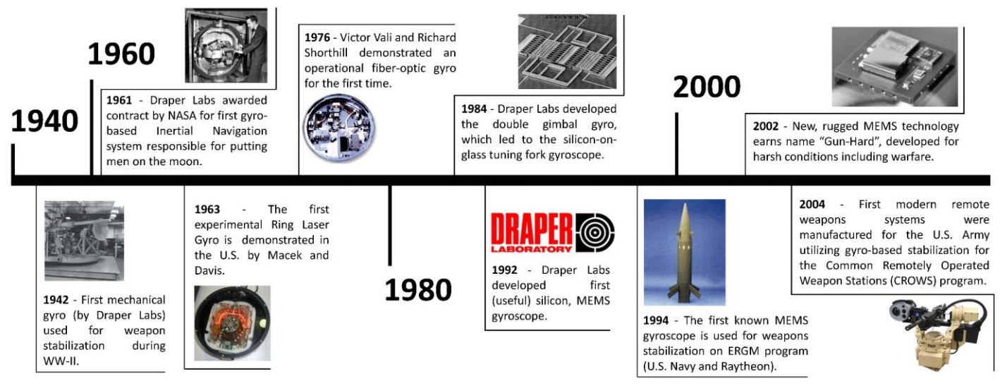
After the invention of the mechanical gyro came the Ring Laser Gyroscope (RLG). The first experimental RLG was demonstrated in the U.S. by Macek and Davis in 1963(6) . One of the initial largest benefits of the RLG (especially in the world of weaponry stabilization) was that the RLG was affected minimally, if at all, by accelerations and shock.
In 1976, Victor Vali and Richard Shorthill demonstrated an operational Fiber-Optic Gyroscope (FOG) for the first time. By the end of the 1980's many were hesitant to use the RLG due to its larger size, weight and power requirements over new FOG devices. Another benefit of FOGs during this time was their immunity to radiofrequency and electromagnetic interference. With fear on the rise for a new generation of electronic warfare, and media outlets like the New York Times speaking of imminent disaster from Nuclear Electro-Magnetic Pulses (NEMP)(7) , military suppliers began to look at the FOG with increasing interest.
In 2004 FOG devices were being utilized in the first official RWS manufactured for the U.S. Army under the program “Common Remotely Operated Weapon Stations (CROWS)”. By 2010 many initially smaller companies, like KVH were able to win multi-million dollar U.S. Army contracts using this fiber-optic technology(8).
So what happened to make the now recognized Microelectromechanical Systems (MEMS) take over the market?
MEMS, The Future of Stabilization
The first stepping stone to create the well known MEMS gyroscope was the double gimbal gyroscope, which became the silicon-on-glass tuning fork gyroscope developed in 1984(9). This technology is what allowed Charles Draper to produce the first MEMS gyroscope in Draper Laboratory in 1992(4). Although this unit's performance was mediocre at best, one of it's initial and immediate benefits was lower manufacturing costs, power requirements and smaller size in comparison to RLG and FOG units.
Spotlight
Charles Stark Draper
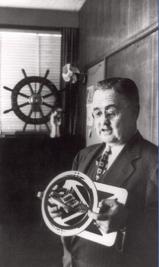
Born October 2, 1901 “Doc” Draper was the director and founder of MIT’s Instrumentation Laboratory. With a pilots license and a desire to learn, much of his professional career was spent developing inertial navigation equipment. By the time of his passing in 1987, Draper had been given more than 70 honors and awards for his work internationally, shaping the future of gyro-based stabilization and navigation equipment.
Also in 1992, the Defense Advanced Research Projects Agency (DARPA) identified MEMS sensors as an emerging technology, critical to the nation’s security needs. As a result, DARPA formally established the MEMS Program(10). This investment by the United States Department of Defense (DOD) led to a funded research that advanced at an increased rate; making MEMS technology that was more robust and with increasingly better performance. Gaining traction, MEMS began to shine over conventional FOG and RLG technologies. Here is a summary of MEMS technology improvements and advancements that came as a result of the MEMS Program(11):

1. Space Savings
MEMS devices are extremely space efficient. Available in the form of chips, these devices can be fitted on electronic circuit boards as small as a few millimeters in width.
2. Digital Interfacing
Digital signaling meant that signals could now be encrypted and users could now rewrite data formats in a matter of hours rather than weeks. Additionally, digital interfacing meant that two-way communication could be established instead of using previous methods which required a cable for each direction of communication.
3. Performance
Variable performance allows users to meet application needs without paying extra. Evolving technology means improvements in the performance of MEMS gyroscopes. Tactical and Navigational performance are now available solutions.
4. Rugged
MEMS has no moving components unlike Dynamically Tuned Gyroscopes (DTG), or RLG and hence, completely maintenance free.
The "Gun-Hard" MEMS
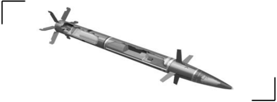
The first known use of MEMS gyroscopes for weapon stabilization dates back to 1994 on the Extended Range Guided Munition (ERGM). This program was started by the U.S. Navy and the contract was fulfilled by Raytheon(12) . As a result of this program, MEMS gyroscopes quickly evolved. One of the projectiles used for this project, the EX-171, is shown below(13).
By 2002 a new MEMS-based gyroscope solution was emerging, designed for stabilization and orientation monitoring in the advanced weapon industry. These MEMS emerged due to DARPA launching two new programs: Nano Mechanical  Array Signal Processors (NMASP) and Harsh Environment Robust Micromechanical Technology (HERMIT). Built to withstand intense environments, many of these systems took on the name "GunHard" IMU’s(14) and by 2004 private companies such as Honeywell, AIS Inc, Raytheon, Inertial Labs Inc. and Colibrys (later purchased by Safran in 2013) were marketing their new lost-cost replacements to traditional FOG and RLG-based solutions for guided munitions and remote weapons stations.
Recent Innovations to RWS
Stabilization Upgrades
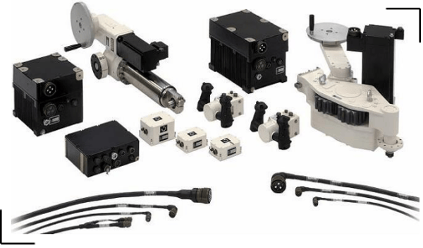
Vibrations will always negatively affect any system by saturating data to some extent. To combat this, Curtiss-Wright has recently released a Turret Drive Servo System (TDSS) that mitigates unwanted vibrations and provides a substantial upgrade to revolutionize stabilization for turrets and pointing systems(15). This system (photographed below) is installed as a kit and can be custom ordered for many different platforms.
Weapon Enhancements
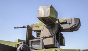
Another American defense company, EOS Defense Systems USA, Inc., announced a new RWS that is now built for more than just low power artillery. This RWS, the EOS R400S Mk2 remote weapon (shown below), is an electro-optically stabilized weapons station that fires Javelin missiles (FGM148) for anti-tank applications in addition to the more traditional Northrup Grumman M230LF Bushmaster gun(16).

Carrier Adaptability
Outside the United States, companies like Leonardo SpA in Spain are creating RWS that are designed for more than just ground vehicles. These automatic aiming systems incorporate target detection, tracking, and autonomous operation; specifically for fixed-wing aerial platforms. Approved within the last year but originally filing to patent their design in 2011(17), Leonardo SpA continues to innovate and improve systems by predicting future technologies that will be used in industry almost a decade later.

Inertial Labs Solutions
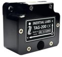
TAG-200 and TAG-300
The TAG product line consists of two-axis and three-axis gyroscopes specifically engineered to offer highly accurate real-time tracking of an object’s angular velocities. As a result, these products allow for the offset of angular rates to factor in turn and tilt, stabilizing electro-optical systems and RWS.
The TAG product line enables Inertial Labs to better serve customers with highly specialized projects that track angular rate data only, offering an exponentially smaller and lighter product ideal for limited space and weight capacity, whether airborne or groundbased. By comparison, fully integrated inertial measurement units (IMU) can be used in a variety of situations, tracking multiple data types to provide data on orientation, position, and velocity.
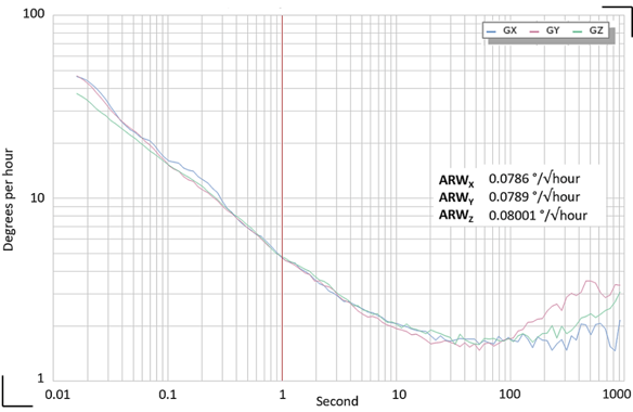
The TAG-200 and TAG-300 feature Inertial Labs MEMS Tactical grade gyroscopes that have a bias in-run stability of 2 °/hour with an Angular Random Walk (ARW) of 0.08 °/√hour. The image above shows the results of an Allan Variance test for measuring gyroscope noise.
IMU-P Tactical
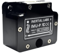
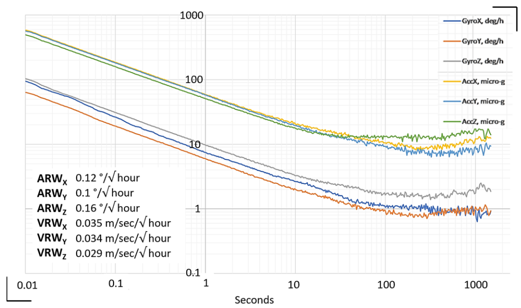
For other applications, users need to take advantage of more than just gyroscope data. The IMU-P Tactical utilizes tactical grade gyroscopes and accelerometers. Depending on your application, Inertial Labs offers two different tactical grade solutions, each with it’s own benefits. The IMU-P Tactical-A offers a sensor fused gyro-based solution with 1 °/hour gyro bias in-run stability with an ARW of 0.2 °/√hour. Alternatively the IMU-P Tactical-S has a lower ARW of 0.08 °/√hour with a gyro bias-in run stability of 2 °/hour. End-users continue to benefit from the sensor solutions from Inertial Labs by only paying for what is needed to meet project requirements. Why pay more when it is not needed? The IMU-P Tactical-A was tested in an Allan Variance test for both ARW and VRW using the configurable 15g accelerometer. Results of this test can be seen in the plot below.
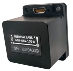
IMU-NAV-100
Over the years, MEMS devices have continued to improve in both performance, and 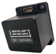 accessibility. The navigational grade IMU’s for years have been reserved for systems that utilize FOGs and RLGs. In recent years however, Inertial Labs has continued to move the ball forward, bringing end users the highest performing devices on the market at the lowest cost.
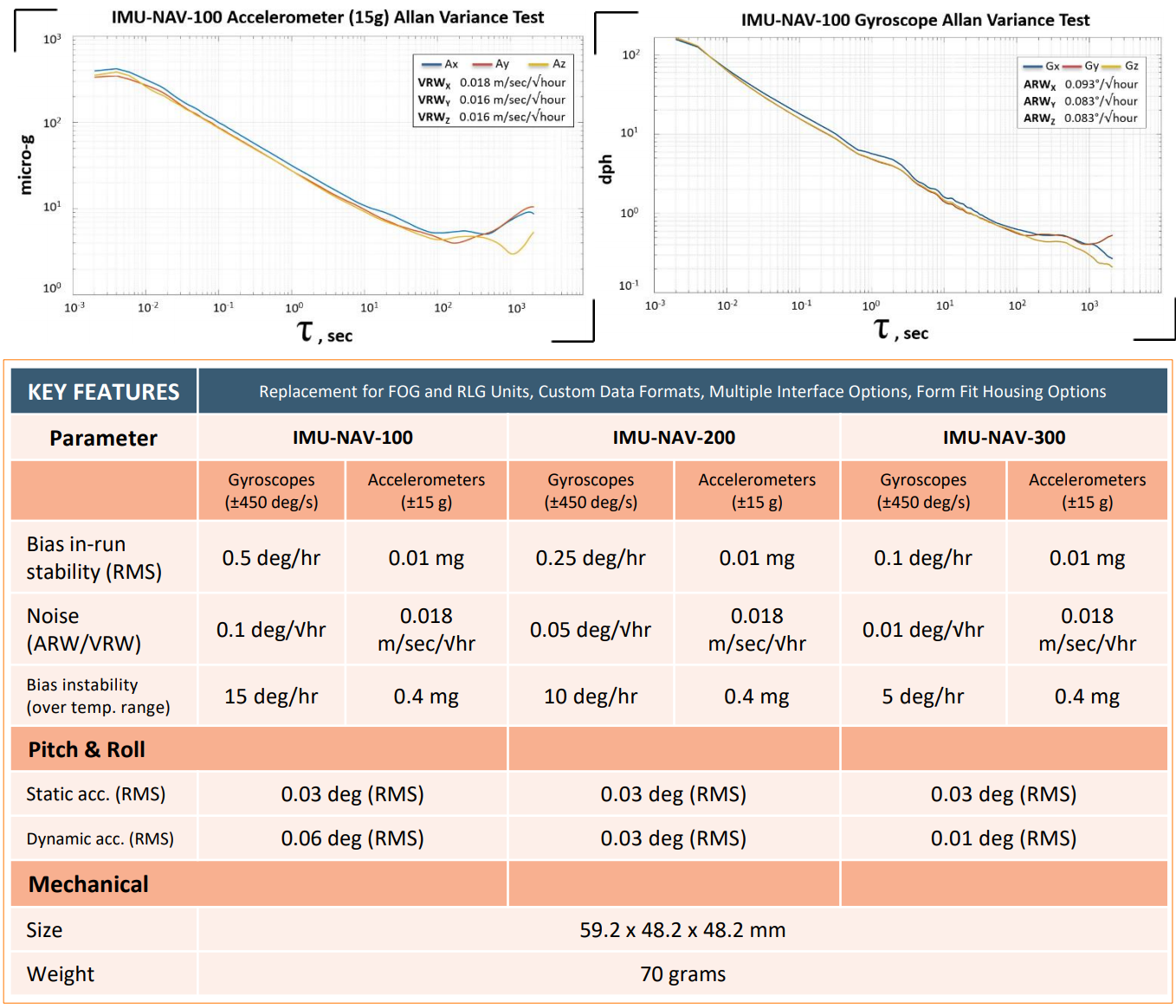
The all-new IMU-NAV product line is the latest addition the Inertial Labs Advanced MEMS sensor-based family. This fully calibrated, temperature compensated, mathematically aligned to an orthogonal coordinate system does not fall short of the Inertial Labs motto: “Attitude is Everything”. It is manufactured to impress. The IMU-NAV-100 is just the first of three navigational grade IMU’s that are now available from Inertial Labs. Allan Variance tests have proven performance through repeatable trials. Plots for gyroscope and accelerometer noise for the IMU-NAV-100 can be seen below. Additionally, the table at the bottom of the page features key performance characteristics between the three new models of navigation grade IMU’s from Inertial Labs.
Bibliography
1. Greene, Ben A., and Steven A. Greene.
2. Erwin, Iwan M., and Ary S Prihatmanto. “Motor Driver Program on Heavy Machine Gun Model for Remote Controlled Weapon
Station (RCWS).” Motor Driver Program on Heavy Machine Gun Model for Remote Controlled Weapon Station (RCWS) - IEEE
Conference Publication, IEEE, 3 Sept. 2013, ieeexplore.ieee.org/document/6588107.
3. Garner, Russel S, et al.
4. Barbour, N., et al. The Charles Stark Draper Laboratory,
pdfs.semanticscholar.org/160a/e09c33db0eafc239289cc9718c923541f599.pdf.
5. “The Little Top That Aims a Gun.” Popular Science, July 1945.
6. Andrews, D A, and T A King. “Journal of Physics D: Applied Physics.” Investigation of a Multi-Oscillator Ring Laser with Magneto-Optic
Bias, https://iopscience.iop.org/article/10.1088/0022-3727/27/9/003/pdf.
7. Burnham, David. “U.S. FEARS ONE BOMB COULD CRIPPLE THE NATION.” The New York Times, The New York Times, 28 June 1983,
www.nytimes.com/1983/06/28/science/us-fears-one-bomb-could-cripple-the-nation.html.
8. “KVH Industries Reports First Quarter 2010 Results.” KVH Industries, Inc., ir.kvh.com/news-releases/news-release-details/kvhindustries-reports-first-quarter-2010-results.
9. Weinburg, Marc S. How to Invent (or Not Invent) the First Silicon MEMS Gyroscope.
10. Tang, William C. “MEMS Program at DARPA.” MEMS Program at DARPA,
http://www.las.inpe.br/~jrsenna/AerospaceMEMS/Resenhas/4559_1.PDF.
11. Gyroscopes And Their Types. Aeronsystems, aeronsystems.com/gyroscopes-and-their-types/.
12. Barbour, N., et al. “Inertial MEMS Systems and Applications .” Inertial MEMS Systems and Applications, pg. 1.
13. EX-171_Extended_Range_Guided_Munition, https://upload.wikimedia.org/wikipedia/commons/0/06/EX171_Extended_Range_Guided_Munition.png
14. Barbour, N., et al. “Inertial MEMS Systems and Applications .” Inertial MEMS Systems and Applications, pg. 3.
15. Techbriefs Media Group. “Turret Aiming and Stabilization System.” Home - Tech Briefs, 2 Feb. 2018,
www.aerodefensetech.com/component/content/article/adt/features/application-briefs/28394.
16. Frahan, Alain Henry de. “EOS R400S Mk2 Remote Weapon Station Fires Javelin Missiles and Bushmaster Gun.” Global Military
Army Magazine Defence Security Industry Technology News Exhibition World Land Forces - Army Recognition, 20 Apr. 2020,
www.armyrecognition.com/april_2020_news_defense_global_security_army_industry/eos_r400s_mk2_remote_weapon_station_fire
s_javelin_missiles_and_bushmaster_gun.html
17. “ES2736275T3 - Remote Weapon Station, Particularly for Airplanes, Such as Fixed-Wing Aircraft.” Google Patents, Google,
patents.google.com/patent/ES2736275T3/en?q=remote+weapons+station&oq=remote+weapons+station.
Trademark Legal Notice: All product names, logos, and brands are property of their respective owners. All company, product and service names used in this document are for identification purposes only. Use of names, logos, pictures and brands does not imply endorsement. Electro Optic Systems Pty Ltd, Popular Science, NASA, Draper Laboratories, New York Times, KVH, MIT, Raytheon, Honeywell, AIS Inc., Colibrys, Safran, Curtiss-Wright, EOS Defense Systems USA, Northrup Grumman and Leonardo SpA are trademarks of its affiliates or its respective owners, registered in many jurisdictions worldwide.