Live Training, Limits of Today
“Train as you fight, fight as you train”, that is a mantra that has circulated in the live training community for 30+ years. Simply put, the training a soldier does should ultimately be 100% representative of what they do in the fight. Whatever cannot be simulated properly in training is unlikely to be performed adequately in battle.
Thirty years later, we are still missing the mark. Live force on force training, the most realistic and battle specific training done for soldiers today, is not a true simulation of “the fight”. It does not fully utilize all the different weapons at the disposal of the military. It essentially breaks down to a reasonable simulation of small arms weaponry and engagements thereof using laser-based technologies. However, indirect fire and call for fire activities, which are inherently impossible to be represented using laser technology, are largely lost in live force-on-force training completely.
With current advancements in the fields of artificial intelligence, augmented reality, and head mounted display systems, such as the Integrated Visual Augmentation System (IVAS), there is renewed hope that incorporation of more advanced weapons into live training may actually be possible and may be right around the corner. However, the successful development and implementation into force-on-force training of weapons such as grenade launchers, mortars, and artillery is far from a simple task. Regardless of the magic expected within IVAS there are fundamental truths that must be achieved before anything will be successfully fielded.
There must be an adequate way to realistically represent all the different weapons including: kill/no-kill scenarios, blast effects, unencumbered weapon usage, and accurate assessments of where virtual rounds are landing in the training environment during the exercise.
A Problem in Search of a Solution
The incorporation of indirect fire weapons clearly has a number of stumbling blocks to overcome, but perhaps the most substantial is the ability to predict with ballistic accuracy the landing of rounds fired virtually within the exercise. Weapons such as mortars and artillery can engage at long range, capable of reaching targets miles away. Small errors in understanding the exact direction of fire for the round can lead to significant errors in the location of where virtual rounds have landed, leading to improper training.
Over a decade ago, Inertial Labs Inc was involved in some of the US Army’s earliest efforts to investigate potential methods to integrate indirect fire and counter defilade weapons into live training. Multiple prototype and demonstration efforts were undertaken to offer the Army a glimpse of potential ways to incorporate augmented and/or virtual reality into live training specifically for the use of indirect fire weapons. These systems typically involved a fully tracked display technology that was linked to a pointing device mounted to the weapon that then provided the ability to display virtual entities, ie. blast effects, in the real world.
In the course of these different efforts one thing became abundantly clear, the technology for determining the barrel azimuth and elevation for the different weapons did not exist. Initial efforts centered on the use of traditional inertial sensor systems known as attitude and heading reference systems; comprising of gyroscopes, accelerometers, and magnetometers. The idea being that if the magnetic sensors could be calibrated on the different weapons, they would be able to then provide an azimuth reference with respect to true north. Accelerometers would provide the reference relative to gravity, and gyroscopes would provide real-time tracking of the change in orientation at high frequency to track through movements.
Photos of the initial prototype system, the Weapon Orientation Module (WOM), being tested on various weapons are shown in Figure 1 below.
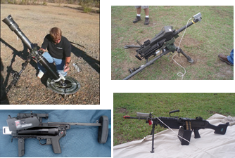
Figure 1: Inertial Labs WOM mounted on 81mm mortar, Mk19, M320, and M249 for accuracy testing
Although the WOM showed promise, achieving accuracies better than 1deg on mortar systems and 0.5deg on smaller arms, ultimately the downfall for any system relying solely on traditional inertial approaches alone, was the reliance on magnetic sensing and magnetic calibration. Magnetic calibration, even in the simplest case, requires manipulation of the weapon in ways that are impractical for soldiers in the field. Furthermore, in the case of weapons that make use of blank fire, it was determined from testing efforts that the magnetic interference from the weapon changes after firing causing the system to lose accuracy during operation.
Figures 2 and 3 below provide graphical results from tests performed on both the M4 and M240 weapons with blank fire. The test results show the magnetic field data from shot to shot including both single shot and burst examples. Before and after each shot the weapon was stabilized on target to check azimuth against the actual for each given target.
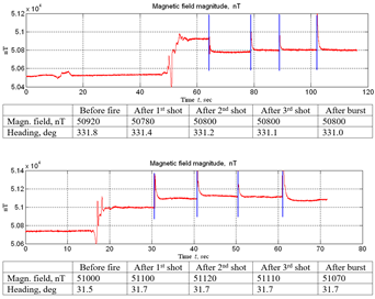 Figure 2: M4 Blank Fire Test Sequences and Results
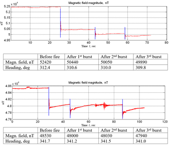 Figure 3: M240 Blank Fire Test Sequences and Results
From these data sets it is evident that weapon firing has an effect on the magnetic interference from the weapon. In each example shown a relatively large initial magnetic field shift, 100s of nanoteslas up to almost 2000 nanoteslas in the most severe case, is witnessed that appears to stabilize for subsequent fires. This shift in magnetic field interference causes a shift in azimuth determination, 0.5 deg and up to over 1 deg in the most severe case. As a result, it was determined that magnetic solutions, although readily available, small, and low-cost, were not likely viable options for fielding. Should advances occur that would include auto-calibration or auto-correction of magnetic based errors, then such technology could be considered in the future.
In addition to pure inertial solutions, Inertial Labs also investigated through different prototype and test efforts potential uses of gyro-compass, celestial, and dual antenna GNSS solutions. All were found to be impractical options either from SWAP-C related issues or performance related issues.
In addition to pure inertial solutions, Inertial Labs also investigated through different prototype and test efforts potential uses of gyro-compass, celestial, and dual antenna GNSS solutions. All were found to be impractical options either from SWAP-C related issues or performance related issues.
The final effort conducted involved the incorporation of optical tracking techniques originally developed for ground robotics applications that utilized simultaneous location and mapping (SLAM). Making use of optical tracking, the system is able to mitigate the risks caused by changing magnetic environments. The optical system essentially replaces the use of magnetic sensors entirely during normal operation. Additionally, with this added azimuth reference the optical solution provides a potential for incorporation of auto-calibration and auto-correction of magnetic errors.
Enter the Optical Inertial Fused Weapon Orientation Module (OptoWOM)
The resulting development finalized into the completion of a Kalman filter, Figure 4 below, that integrated optical based orientation as part of the system solution. This system replaced the ongoing reliance on magnetometers in the Kalman filter with optical azimuth determination. Initial azimuth is determined using the magnetic sensors through the system initial alignment, but during general operation the system relies predominantly on the optical solution for the ongoing azimuth correction of the filter.
Resulting tests conducted on a prototype OptoWOM fabricated under an SBIR Phase III effort for live training showed the ability to track barrel orientation to within 0.3deg (5mils) azimuth and 0.1deg (2mil) elevation and led to initial interest from a surprising customer. As the live training community was essentially tabling their efforts to continue developing solutions for indirect fire weapons in live force-on-force training, the tactical community was busy looking for new and interesting solutions to a different problem, man-portable fire control.
They were actively pursuing new technologies that could act as pointing devices for fire control solutions for dismounted mortar systems: 81mm and 60mm mortars.

Figure 4: OptoWOM Optical/Inertial Fusion Filter
WULF
Engineers within Picatinny Arsenal who had previously worked on the development of the Mortar Fire Control System – Dismounted (MFCS-D) for the 120mm mortar had a vision to create a new digital fire control solution that would be low cost and man-portable allowing for use on smaller mortar systems such as the 81mm and 60mm mortars. After initial efforts centered around a more traditional inertial sensor approach – not dissimilar in technology to the WOM device – they too came to the conclusion that traditional inertial sensor approaches were not adequate. Also, gyro-compass solutions, such as those used in MFCS-D, were not practical from a SWAP-C standpoint for the smaller guns and were not man-portable by any means. Celestial technology was not reliable enough under many conditions. Finally, GNSS solutions had one fatal flaw, they relied on the availability of GNSS which can not be guaranteed on the field of battle.
Once discovering the work that had been originally started within the Army Research Laboratory – Human Research and Engineering Directorate (ARL-HRED) within the SBIR Phase III efforts, the final puzzle piece for a man-portable dismounted fire control system appeared to be there and the groundwork for the Weaponized Universal Lightweight Fire Control (WUL)F was born.
WULF consists of three major components: the Gun Computer, the Weapon Pointing Device (WPD or OptoWOM), and the System Battery. The Gun Computer provides the gunner with the information needed to direct the movement of the gun tube in order to properly engage an enemy target. It shows the changes required in elevation and azimuth in mils and as the gunner moves the tube correctly towards the required pointing vector the azimuth and elevation numbers descend towards zero. Once reaching the final required orientation the gunner is notified that the weapon is “layed” (on target) and firing can commence. To do this, the system relies on data from the Fire Direction Center regarding the location of the target and the required gun orientation to engage the target, and then utilizes the data from the Weapon Pointing Device (WPD) mounted on the dovetail mount of the bipod to track the gun tube orientation in order to direct the gunner appropriately.
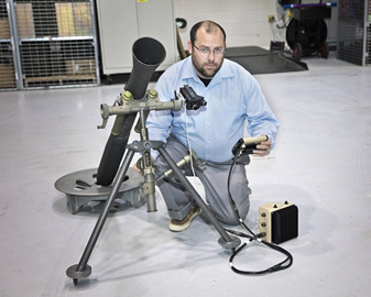 Figure 5: WULF Mounted to 81mm Mortar
Tests conducted with the WULF system by engineers at Picatinny Arsenal using their Bore Elevation and Azimuth Measurement System (BEAMS) confirmed the system’s ability to maintain accuracy to within 3.25mils Azimuth and 2mils Elevation using WPD prototypes completed within the SBIR Phase III efforts.
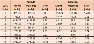
Figure 6: Large Angle Tests of OptoWOM on 81mm Mortar
 Figure 7: Small Angle Test Results of OptoWOM on 81mm Mortar
Continued Developments and Algorithmic Metamorphosis
The initial developments of the optical system relied heavily on features used in simultaneous location and mapping (SLAM) that are used widely in robotics applications today. The system, through the collection of images from onboard cameras, turns the images it is receiving into a series of uniquely identifiable feature points.
Once stored, these optical references are then used to determine current system orientation by comparing the current images (and their corresponding unique features) to the stored reference features. Once reliably matched the system can calculate the orientation shift from the reference features to the current features and provides these data to the Kalman filter.
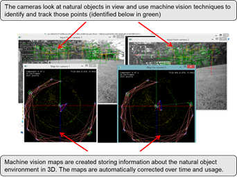 Figure 8: Optical Feature Matching and Mapping Example
Figure 8 above provides an example of images received by the two onboard cameras and how the system turns these images, using techniques of SLAM, into a 3D map of the features in the local environment. These machine vision maps are able to create links between the different reference feature sets that have been collected and make adjustments to those over time in order to create a final bound error, eliminating error drift that would normally be associated with inertial based solutions.
Although initial test efforts showed these methods of optical map creation and adjustment to provide generally accurate results (typically within 3mils), advancements that have been realized in the field of micro-electro-mechanical systems (MEMS) gyroscopes led to a breakthrough in the more recent prototype systems. Quite frankly, other than with small movements of the system, today’s MEMS gyroscopes are able to more accurately determine changes in orientation of the system than optical alone. This is due to the parallax realized by the optical solution from its mounting location on the bipod.
In previous detailed tests conducted it was realized that single movements of the gun tube may generate errors up to 3mils due to the parallax - increasing risk of exceeding error limits, especially early in use. In the map-based system, these errors would reduce over time and usage, but could lead to initial errors that are unacceptable. However, using state-of-the-art MEMS gyroscopes, in contrast, singular movements of the gun tube have been found to only generate errors up to 1mil maximum within any single movement. Thus, in order to keep errors minimized, the algorithm was adjusted.
The filter was modified to become a smart filter, one that would understand when gyro orientation needed to be weighed more heavily versus when optical orientation should be weighed more heavily. Furthermore, the embedded mapping system was additionally adjusted accordingly to where the system – rather than building a series of linked reference feature sets based solely on optical data – would simply build a series of unique reference sets that were a merge of gyroscopic data and optical data. These provide the luxury of continuing to have a bound, non-growing error source over time, but without the inherent errors seen in the optical only reference creations that are caused by system parallax.
Current testing using this method has shown an ability to reliably operate within a bound overall system error of 3mils azimuth. Comparing that to the original system that at times, although rare, was found to see as much as 3mils error from a single barrel move. This discovery was a major shift in the approach that has greatly benefitted the system performance.
One area of significant improvement that resulted from this algorithmic shift is in operation behind defilade. Defilade relates to the use of a structure to protect the mortar system. Figure 5 below shows a typical defilade configuration. The challenge for the optical system here is that the visible features available are all very near to the optical system, thus exacerbating the effects of parallax error. Based on the new algorithm’s “smart filter” operation there is no difference in performance regardless of the optical environment.
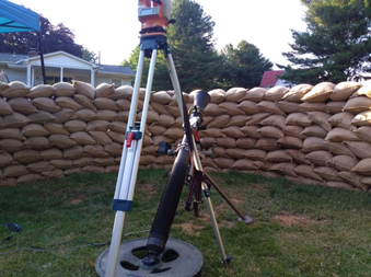
Figure 9: 81mm Mortar System Test Conducted Behind Defilade
Adaption of WULF to Live Training
Due to the successes accomplished in the ongoing developments of the WULF system in the tactical environment and the relative lack of success in finding any practical alternative solutions to meet the needs of the live force-on-force training community for indirect fire weapons, the US Army has now begun something that is quite rare. Communications between engineers within the live training community and those in the tactical community have concluded with an effort to adapt the solution that was developed for the tactical fire control community into a training device for the live training community.
Currently, engineers at Picatinny Arsenal are undertaking an effort to complete a training solution for both mortar systems and the Mk-19 grenade launcher based largely off the WULF system. However, instead of taking data from a Fire Direction Center (FDC) and advising a gunner on how to move the gun tube to engage an enemy, in the training scenario the system will allow the gunner to make use of current aiming technologies to aim the weapon exactly as they do today. Using a special mount that allows both the current aiming sight for the mortar and the WPD to be mounted simultaneously, the WPD provides the gun tube azimuth and elevation, and the ballistic computer using the NATO Armaments Ballistic Kernel is then able calculate the round impact points for moments of fire.
In a live force-on-force training exercise, the gunner will use the mortar weapon as defined in the mortar tactics, techniques, and procedures (TTPs). The system aim points (azimuth and elevation of the weapon) are calculated by the FDC and verbally called out to the gunner just like is done in the tactical environment. The gunner and assistant gunner use the M67 sight unit to aim the weapon on the FDC provided aim points. The mission data (round type, charge, and fuse) gets inputted into the “training computer”. The assistant gunner then pretends to drop a round and the gunner presses “Shot” on the computer. All actions performed by the training computer in the initial implementation of the system could also easily be automated through the use of an electronic simulation round. In this case, all information on round type, charge, and fuse would be programmed into the virtual round and firing would be built into the round as well.
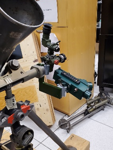 Figure 10: WULF on Mortar
The training system then calculates where the round would have impacted based on the azimuth and elevation of the weapon system and the round data and creates an accurate fly out map of the round trajectory. This trajectory is used to determine round impact using topographic maps. With this data, an impact point and radius of effect of the round can be used inside multiple training systems to signal a hit/kill based on the weapons actual aim and not just where it was told to aim.
Likewise, for the Mk-19, the WPD would provide the gun azimuth and elevation of the Mk-19 that would be utilized in the same manor. In the case of the Mk-19 however, this would also be used to provide the ability for the system to provide virtual blast effects into the gunner’s view. These either could be provided via a gun mounted display or through a head mounted display system; whichever was determined to be more desirable.
The significance of finding a practical solution to the problem of proper weapon orientation tracking for indirect fire weapons in live training can not be overstated. Real tracking of actual tube azimuth is the only way to properly implement any of these weapons into the game. Also, by using technologies developed for tactical systems, the solution immediately supports inclusion of those future systems into live training inherently, not requiring new developments or new technologies once those systems are fielded.
A Brief Look Into the Future
Although initial efforts currently underway have focused on the need for indirect fire solutions, the same technology lends itself well towards the future desire to solve the problem of direct fire, small arms weapons as well. Advancements in camera technologies and continued advancements in onboard computing technologies and MEMS sensor technologies show tremendous promise towards completion of a similar system that could be gun mounted on small arms taking the place of current laser based systems.
The challenge for small arms though extends beyond those of typical indirect fire systems. Dynamic movements of dismounted soldiers and quick engagements will require those developing such systems to consider new methods to solve the problem. Methods that include object detection and recognition technologies and rapid 3d mapping will likely need to be a major part of any efforts to solve that problem.
Today’s state of the art in UAV payloads using Lidar, for example, show great promise in the creation of highly accurate and detailed maps of local environments. Completion of a 3D map provides the possibility of providing an abundance of visual references that can be identified by the optical system and provide true north references that can be utilized in weapon orientation tracking.
Figure 7: Small Angle Test Results of OptoWOM on 81mm Mortar
With ongoing advancements in optical technologies, the idea of this added capability being realized within the OptoWOM is becoming a reality. As such, the idea of the eBullet for all weapons in live training becomes more and more realizable.

References
[1] Healy, Melissa. Feb 26, 1991. “In Face of Death--What Makes Soldiers Disregard Instinct? : Training: Reflex, loyalty and hatred of the enemy can be cultivated to ensure that GIs fight instead of flee” Los Angeles Times.
[2] Freedberg, Syndey J. Nov 30, 2020. “eBullet Brings Richer Realism to Army Training: No More Laser Tag” www. BreakingDefense.com.
[3] Lopez, Ed. May 10, 2017. “The Road to Providing a Faster, More Accurate Mortar Firing System” www.USArmy.mil.
[4] Calloway, Audra. Dec 2, 2011. “Picatinny Provides Soldiers with Quicker, Safer, Mortar Fire Control System” www.army.mil.
[5] Pinto, Robert P. May, 2011. “Bore Elevation and Azimuth Measurement System (BEAMS)”, Joint Armaments Conference, Exhibition and Firing Demonstration Proceedings.
What Do You Think?
At Inertial Labs, we value customer satisfaction and want to continuously provide solutions specifically tailored to today’s problems, while aggressively developing products that tackle tomorrow’s concerns. Your opinion is always important to us whether you are a student, an entrepreneur, or an industry heavyweight. Please share your thoughts on our products, what you would like them to achieve, or just say hello at opinions@inertiallabs.com
Trademark Legal Notice: All product names, logos, and brands are property of their respective owners. All company, product and service names used in this document are for identification purposes only. Use of names, logos, pictures, units and brands does not imply endorsement. The US Army, Picatinny Arsenal, Army Research Laboratory, and NATO are trademarks of its affiliates or its respective owners, registered in many jurisdictions worldwide.