
Last Updated: July 2019
1. HYPACK
1.1. Introduction
The Inertial Labs™ MRU family products (MRU-B, MRU-E, and MRU-PD) are compatible with HYPACK software for hydrographic surveys. HYPACK is Windows-based software for Hydrographic and Dredging Industries. Using the Inertial Labs™ MRU along with the HYPACK hydrographic survey software allows real time data collection and processing for imaging, terrain modeling, and statistical reporting.
For more details about HYPACK software, please visit the website www.hypack.com.
In order to connect MRU to HYPACK it is necessary to do the following:
• To determine a serial port number to which COM1 of the MRU is connected;
• To set the MRU with TSS1 output data format into “Autostart” mode; To set the “Hardware setup” parameters in HYPACK software.
This document provides short description of performing these procedures.
1.2. Preparation
1.2.1. Serial port determination
Before connecting the MRU to the HYPACK software, it is required to determine Serial Port number to which main COM port of the MRU is connected. This section provides short instruction on how to determine the serial port number (for more detailed explanation, please see “MRU GUI User’s Manual” Section 2, “Installation of drivers and configuration of PC parameters”).
Using the cable provided by Inertial Labs, connect the MRU to a PC and start supplying electricity. The MRU LED indicator should light up in yellow, and then change to red. Now the device is ready for operation.
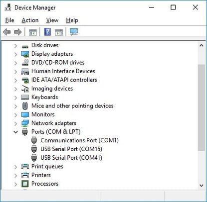
Open “Device Manager” window on your computer (Fig. 1.1). All connected COM and USB ports are listed under the “Ports (COM & LPT)”. COM ports are marked as “Communications Port (COM1)”, where number “N” is a port number assigned by OS.
If you connect the MRU via COM-to-USB converter, then a port is marked as “USB serial port (COMN)”, where “N” is a port number assigned by OS.
Please remember the number of a serial port for further connection to the HYPACK software.
 1.2.2. Auto start mode and TSS1 output format
The HYPACK software requires receiving data from the MRU in standard TSS1 output format. Before connecting the MRU to the HYPACK software, it is necessary to set the MRU into auto start mode and output data format to TSS1.
In the auto start mode, the MRU starts operating automatically after power turns on, with continuous output data in desired data format without any commands from a host computer (please see Section 10.5 “MRU automatic start” of the MRU GUI User Manual for more details).
All available output data formats are listed in “Autostart” drop-down list on “IMU” tab of “Device options” menu as shown of the Fig. 1.2. Please choose TSS1 output data format for the MRU autostart for further connection to HYPACK software.
Also, please specify baud rate of main port of the MRU in “COM Port bps” drop-down list and set required frequency of output data in “Data rate (Hz)” field. Please note that it is critical to ensure that chosen baud rate is capable of handling data throughput with desirable data rate. Table 1.1 contains data package length for TSS1 data format and also maximum measurement rate for each possible baud rate.
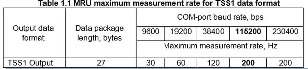
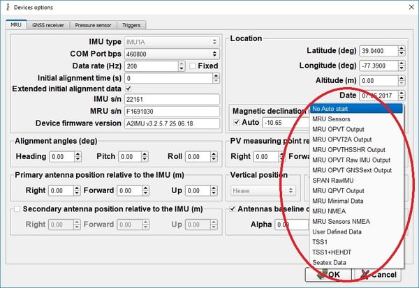 Figure 1.2
After all settings in “Device options” are set, click “OK” button, close MRU GUI and reboot the unit. Once rebooted, the MRU starts outputting data in TSS1 format automatically after the LED turns green.
1.3. The procedure of connecting the MRU to HYPACK
In order to connect the MRU to the HYPACK software, it is necessary to perform the Hardware Setup. This section describes the key steps on how to make MRU and HYPACK software work together.
For more information and detailed description, Inertial Labs recommends to refer to the official HYPACK User Manual (the latest version of the Manual can be downloaded from the official site www.hypack.com).
It is necessary to perform the following steps after launching the HYPACK software:
Step 1 Select “Hardware Setup” from the “Preparation” drop-down list (see Fig. 1.3)
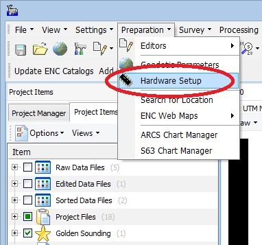 Figure 1.3
Step 2 In the new window (see Fig. 1.4) create new Hardware list by clicking the “New” item in the “File” menu.
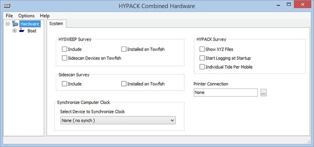 Figure 1.4
Step 3 Please select the “Boat” item in the configuration tree and rename the device, if it is necessary, on the “Mobile” tab. (see Fig. 1.5)
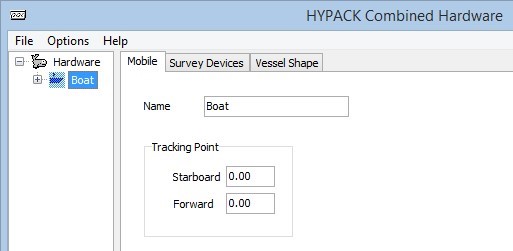 Figure 1.5
Step 4 Please open the “Survey Devices” tab. This tab allows choosing a driver for different types of hardware. In our case, please choose “tss320.dll” driver and click “Add >” button (see Fig. 1.6). “Tss Motion Reference Unit” appears in the “Installed” field as shown on Fig. 1.6.
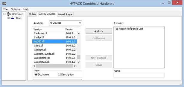 Figure 1.6
Note. For more details about “tss320.dll” driver, please see the HYPACK Common Driver Notes document. HYPACK Common Driver Notes can be downloaded from official website www.hypack.com.
Step 5 In order to configure the MRU COM port connection parameters, please select “Tss Motion Reference Unit” in the configuration tree, and open “Survey connect” tab as shown on Fig. 1.7.
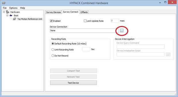 Figure 1.7
Step 6 Click the (...) button next to the “Device Connection” section (see Fig.1.7) and choose “Serial” in the “Connection Type” drop-down list (see Fig.1.8). After that, please set proper parameters in the “Serial Parameters” field (see Fig. 1.9): “Port” – set serial port number determined in section 2.1 of this document; “Speed” – set baud rate that corresponds with the baud rate configured in the “Device options” menu of the MRU GUI Software. Click “OK” button to apply settings.
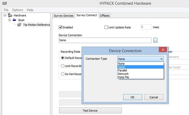 Figure 1.8
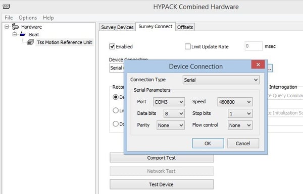 Figure 1.9
Step 7 There are enabled buttons on the “Survey connect”: “Comport Test” and “Test Device”. The “Comport test” allows checking status of serial communication ports and correctness of the MRU connection. If MRU is properly connected, then “Comport Test” window shows the following:
- In the “Status” column - “Connected”;
- In the “Device” column - “Tss Motion Reference Unit”;
- In the “Data” column - real time data from the MRU in the TSS1 format as shown on Fig. 1.10.
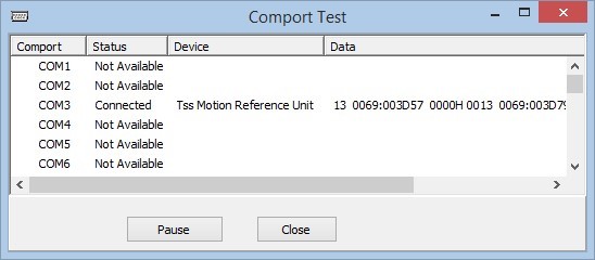
Figure 1.10
Click “Pause” to pause data transfer or “Close” to close the “Comport Test” window.
Step 8 (Optional) Click “Test Device” (Fig. 1.7) button to see the MRU data in TSS1 format with names of measured parameter as shown on Fig.1.11.
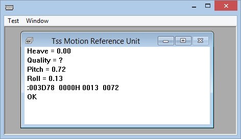 Figure 1.11
The MRU is successfully connected and ready to use with HYPACK software.
2. QINSy
2.1. Introduction
The Inertial Labs™ MRU family products (MRU-B, MRU-E, and MRU-PD) are compatible with QINSy software for hydrographic surveys. QINSy (Quality Integrated Navigation System) is Windows-based data acquisition, navigation and processing software package for Hydrographic industry. Using the Inertial Labs™ MRU along with QINSy hydrographic survey software allows real time data collection and processing for imaging, terrain modeling, and statistical reporting.
For more details about QINSy software, please visit the website http://www.qps.nl
In order to connect the MRU to QINSy it is necessary to do the following:
• To determine a serial port number to which COM1 of the MRU is connected;
• To set the MRU into “Autostart” mode with TSS1 output data format; To set the “Hardware setup” parameters in QINSy software.
2.2. Preparation
2.2.1. Serial port determination
Before connecting the MRU to QINSy software, it is required to determine a serial port number to which main COM port of the MRU is connected. This section provides short instructions on how to determine a serial port number (for more detailed explanation, please see “MRU GUI User’s Manual” Section 2, “Installation of drivers and configuration of PC parameters”). Using the cable provided by Inertial Labs, connect the MRU to a PC and start supplying electricity. The MRU LED indicator should light up in yellow, and then change to red. Now the device is ready for operation. Open “Device Manager” window on your computer (Fig. 2.1). All connected COM and USB ports are listed under the “Ports (COM & LPT)”. COM ports are marked as “Communications Port (COM1)”, where number “N” is a port number assigned by operating system. If you connect the MRU via COM-to-USB converter, then a port is marked as “USB serial port (COMN)”, where “N” is a port number assigned by operating system. Please remember the number of serial port for further connection to QINSy software.
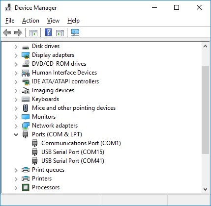 Figure 2.1
2.2.2. Auto start mode and TSS1 output format
QINSy software requires receiving data from the MRU in the standard TSS1 output format. Before connecting the MRU to QINSy software, it is necessary to set the MRU into auto start mode and output data format to TSS1.
In auto start mode, the MRU starts operating automatically after power turns on, with continuous output data in desired data format without any commands from a host computer (please see Section 10.5 “MRU automatic start” of the MRU GUI User Manual for more details).
All available output data formats are listed in “Autostart” drop-down list on the “IMU” tab of the “Device options” menu as shown of the Fig. 2.2. Please choose TSS1 output data format for the MRU autostart for further connection to QINSy software.
Also, please specify baud rate of the main port of the MRU in “COM Port bps” drop-down list (the value 115200 is recommended, see Fig. 2.2) and set required frequency of output data in “Data rate (Hz)” field. Note that it is critical to ensure that chosen baud rate is capable of handling data throughput with desirable data rate. Table 2.1 contains data package length for TSS1 data format and also maximum measurement rate for each possible baud rate.
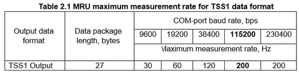
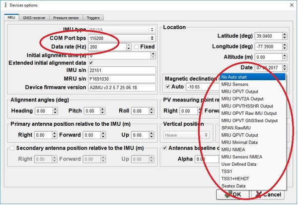 Figure 2.2
After all settings in “Device options” are set, click “OK” button, close MRU GUI and reboot a unit. Once rebooted, the MRU starts outputting data in TSS1 format automatically after LED turns green.
2.3. The procedure of connecting the MRU to QINSy
In order to connect the MRU to QINSy software, it is necessary to perform Hardware Setup. This section describes key steps on how to make MRU and QINSy software work together.
Perform these three procedures in order to launch and get QINSy software ready to connect to MRU:
Procedure 1. Creating a new empty template database
QINSy pulls and saves data like configuration and settings of vessel configuration, geodetic parameters, I/O parameters etc. in a relational database.
Procedure 2. Defining parameters in the geodetic wizard
The geodetic parameters wizard allows a user to define all parameters such as the survey datum, the projection type and projection parameters.
Procedure 3. Defining an object
An object on which equipment, or measuring systems are installed must be defined in QINSy Survey software. An object can be a survey vessel, ROV, SSS fish, drilling rig or a barge.
Once procedures mentioned above are done, the next and the final step is defining a system. System definition procedure is specific per particular equipment. In the next section, it is assumed that Qinsy is being connected to Inertial Labs™ MRU.
For more information and detailed description, Inertial Labs recommends referring to the official QINSy instructions on QPS website: https://confluence.qps.nl/qinsy/en/2-qinsydatabase-setup-35587354.html.
MRU definition
Having defined geodetic parameters and an object, the next steps are to define the MRU or other systems that are going to be used during the survey.
Step 1 Launch the QINSy software (see Fig. 2.3).
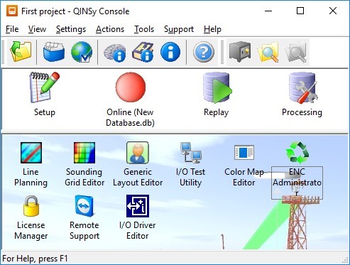 Figure 2.3
Step 2 Start the Setup module from the Console by double clicking on the "Setup" icon in the upper left half of the window. It is assumed that there must “New Database” (see Fig. 2.4) appear in the list, according to steps performed in the previous section, Procedure 1 “Creating a new empty template database”.
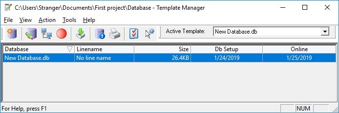
Figure 2.4
Step 3 Open database by double clicking on the name (see Fig. 2.5).
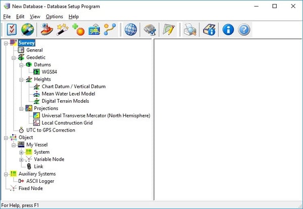
Figure 2.5
Step 4 The next step is to define systems that are going to be used during the survey. Systems include measurement devices like MRU, GPS, echosounder and gyro compass. To define a new system, click on the icon  . In our case we want to define Inertial Labs MRU (Pitch Roll Heave Sensor). Fill in fields like shown on the Fig. 2.6.
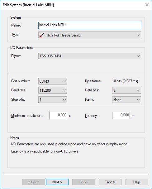 Figure 2.6
Note:
- “Port number” – set the serial port number determined in section 2.1 of this document, “Baud rate” – set the baud rate that corresponds with the baud rate configured in the “IMU” tab of “Device options” menu of the MRU GUI Software (see Fig. 2.2).
- The different output formats are specified in QINSy Drivers and Interface Manual that can be found in the QINSy Console (
 icon, see Fig. 2.3) or in Support Desk section of QPS website: http://www.qps.nl.
Step 5 Click the Next button. Fill in the form following example shown on the Fig. 2.7. Note that the fields in the Location area should be relevant to customer’s needs. Make sure that Type field of Rotation Measurements area is HRP and Sign field of Heave Measurements area is Positive upwards according to TSS1 format.
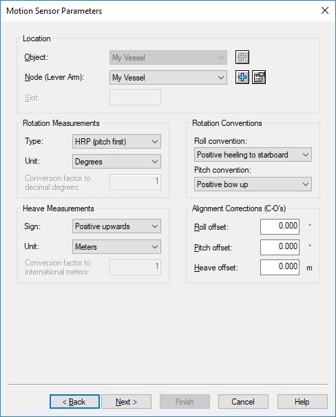 Figure 2.7
Step 6 Click the Next button. Fill in the blank according to your device specification, or leave default values. Press Finish button to complete the MRU definition (see Fig. 2.8).
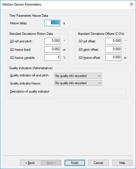
Now MRU is connected to QINSy software.
Step 7 (Optional) It is possible to pre-check performance of the MRU. Power the MRU unit on, click “Online”  from the Console (see Fig. 2.3) and the window shown on Fig. 2.9 will appear.
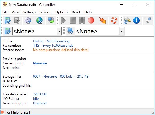 Figure 2.9
Step 7.1 In order to see the MRU data with names of measured parameter, click Display Manager  icon and the window shown on Fig. 2.10 will appear.
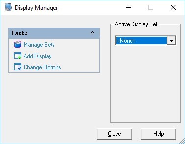 Figure 2.10
Step 7.2 Press Add Display and confirm creation of a new empty set (see Fig. 2.11).
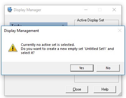
Figure 2.11
Step 7.3 Enter a Title for new display and choose Type “Observation Physics Display” and click OK button (see Fig.2.12).
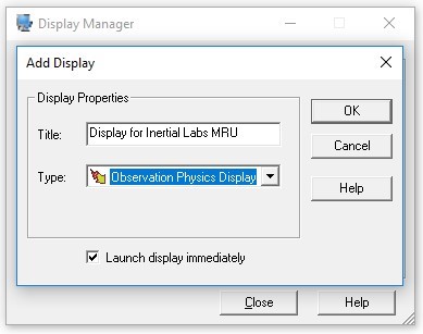 Figure 2.12
Step 7.4 On the next window choose “Inertial Labs MRU” in Available Observations section and press the button. Confirm settings by clicking OK button (see Fig.2.13).
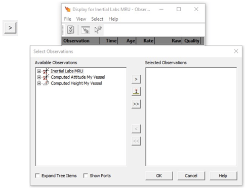 Figure 2.13
The window with live data from MRU becomes available (see Fig. 2.14).
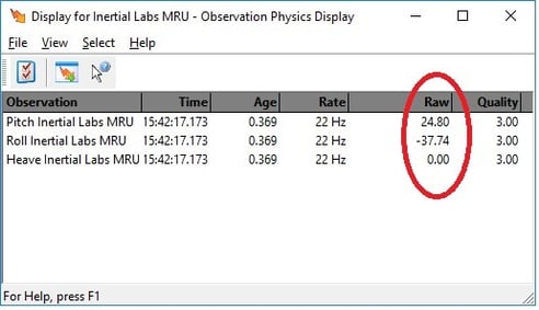 Figure 2.14
It confirms that the Inertial Labs MRU is successfully connected and ready to be used with QINSy software.