Last Updated: October 2019
Purpose: The Inertial Labs INS has five methods of hard and soft iron calibrations for heading calculations.
1. 3D Calibration
Application: The 3D calibration is designed for carrier objects (typically aerial, or marine) that can operate in full heading, pitch and roll ranges. A possible application using this calibration method is bathymetric surveillance.
Calibration Method: At this calibration the carrier object should be rotated in all these ranges. During the INS data accumulation, the object should be rotated in full azimuth, pitch and roll ranges. For example, the object is rotated in the horizon plane (the Z-axis is up) with periodical stops about each 90 degrees for tilting in pitch and roll. After full 360° rotation the object with the INS is turned over (the Z-axis is down) and the procedure described above should be repeated. During this calibration the range of pitch and roll angles changing must be as much as possible.
Reference: Section 6.8.1 of INS ICD
2. 2D-2T Calibration
Application: The 2D-2T calibration is designed for objects that operate in full azimuth range but with limited range of pitch and roll angles such as indirect fire control.
Calibration Method: This calibration procedure involves a few full 360° rotations of the object in azimuth with different pitch angles. After sending the start command to the INS, rotate object in azimuth with approximately constant pitch and roll. This rotation must include one or more full 360 deg turns. Please, correct the time required for such rotation in the «Time of data accumulation» field of the message (Table 6.88) to provide necessary rotation.
Reference: Section 6.8.6 of INS ICD
3. 2D Calibration
Application: The 2D calibration is designed for carrier objects that operate in full azimuth range but with small pitch and roll angles (not more than a few degrees) such as land vehicle applications.
Calibration Method: This calibration procedure involves full 360° rotation of the carrier object in azimuth. During this rotation pitch and roll angles must be as close to zero as possible. After sending start command, rotate carrier object in azimuth with pitch and roll angles close to zero as possible. This rotation must include one or more full 360 deg turns. Please, correct the time required for such rotation in the «Time of data accumulation» field of the message (Table 6.88) to provide necessary rotation.
Reference: Section 6.8.9 of INS ICD
4. VG3D Calibration
Application: The VG3D calibration is designed for carrier objects that can operate in full heading, pitch and roll ranges such as fixed wing UAVs and aircraft. VG3D calibration is similar to 3D calibration but allows performing simpler rotation than is necessary for 3D calibration.
Calibration Method: During the INS data accumulation, the object should be rotated in full azimuth range and maximum possible pitch and roll ranges. Allowed object motion should be agreed with Inertial Labs.
Reference: Section 6.8.5 of INS ICD
5. On-the-Fly VG3D Calibration
Application: Since firmware version 2.6.2.2 the INS provides on-the-fly VG3D calibration. It allows to calibrate INS unit during INS ordinary operation without interruption of INS navigation data calculation and output. This could be possibly used for drone payload applications.
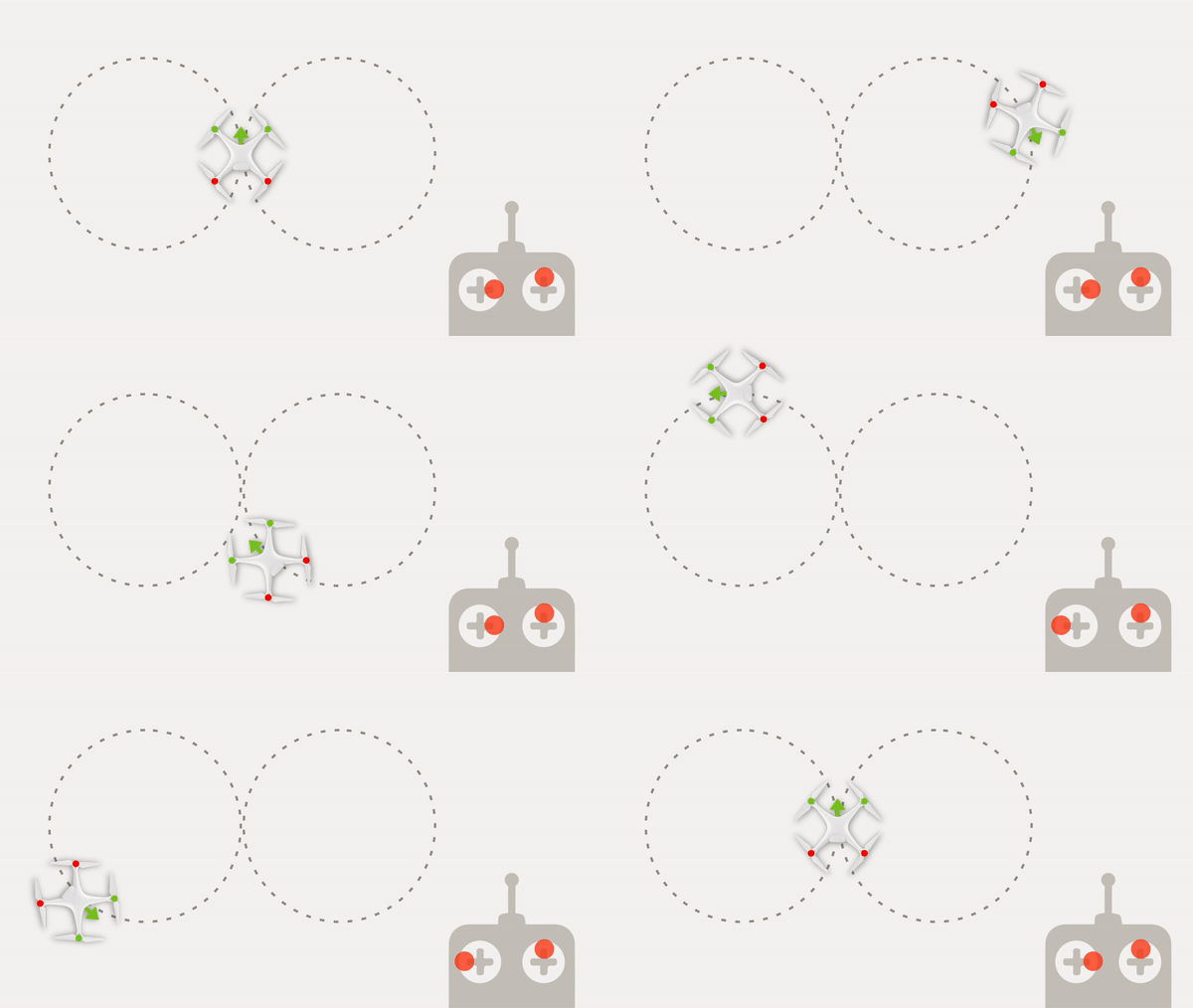
Calibration Method: After sending the start calibration command to the INS, the carrier object with INS unit should be rotated in full azimuth range with maximum possible pitch and roll ranges. For example, airplane should perform at least two full 360° coordinated turns (on the right and on the left, figure eight pattern) with maximum roll angles.

Reference: Section 6.8.12 of INS ICD
