
Purpose: Identify the pin outputs for the GNSS output on the INS-B, INS-P, INS-D, INS-DL
Last Updated: July 2019
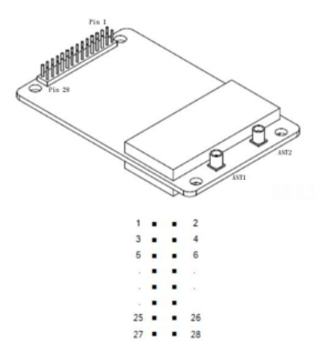
Figure 1. GNSS board with pin numbers identified.
Pinout Description
| Pin | I/O | Description |
| 1 | N/A | Not used |
| 2 | N/A | Not used |
| 3 | N/A | Not used |
| 4 | N/A | Not used |
| 5 | Power | Antenna feed input |
| 6 | Power | Power input |
| 7 | I | SPI Data |
| 8 | I | COM3 input data |
| 9 | I | Reset input |
| 10 | I | Reset |
| 11 | I | Event |
| 12 | I | Reserve |
| 13 | O | COM3 output |
| 14 | Power | GND |
| 15 | O | COM1 output |
| 16 | I | COM1 input |
| 17 | Power | GND |
| 18 | O | COM2 output |
| 19 | I | COM2 input |
| 20 | Power | GND |
| 21 | O | Reserve |
| 22 | Power | GND |
| 23 | O | PPS |
| 24 | I | Reserve |
| 25 | N/A | Not used |
| 26 | N/A | Not used |
| 27 | N/A | Not used |
| 28 | N/A | Not used |
Figure 2. Pinout description for each of the pins on the GNSS board.